6.115: Microcomputer Project Laboratory
Oh boy… this was something for sure.
From the course website: Course topics include optical tomography, multi-axis robot arm control, video and audio signal processing, power electronics including laptop power supplies and fluorescent lamp ballasts, and numeric computation (calculators and floating point calculations). This class is not particularly about learning how a specific microcontroller is programmed, or about designing circuits, or about wiring chips together. We do a little of all of these things, but our real goal is to introduce you to a palette of tools and techniques that let you build what you can imagine. These techniques are much more general than the details of a single processor or programming language. Chips come and go, but successful approaches for engineering design have a life that spans many iterations of a particular technology.
Practical Takeaways
The quiz covered the core technical concepts in the class, but the hardest part was the labs and final project. So, here are some takeaways.
(Generated by Gemini 2.0 Flash Experimental)
1. Learning to Learn
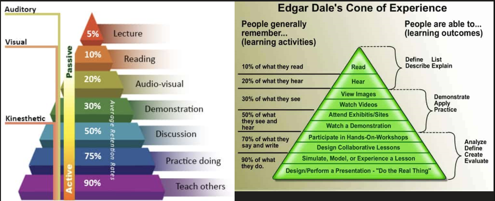
We discussed that learning is not a passive activity. We tend to remember more when we are actively engaged with the material, as opposed to just listening or reading. For example, lecturing is the smallest part of the learning pyramid, and is not very effective. The more we interact with the material - by discussing, practicing, and teaching others - the more we will retain.
The course aimed to shift us from passive learners to active participants. We need to move beyond reading and listening to truly engage with the content. Active learning involves doing, designing, and teaching the material.
2. Lab Notebook Guide
The lab notebook is our scratchpad for designing systems, where we can use computer-generated or hand-drawn schematics.
For each lab, we need to show working hardware and software, demonstrate lab knowledge, have a lab notebook with explanations, and include a commented code appendix. The notebook should explain what we did, how, and why, with clear solutions and labeled schematics/graphs. We can cross out errors and move to new pages, and should note any omitted connections.
Each lab entry needs a title with lab number, name, and date, plus an introduction/goals section. Explanations should be in full sentences, with design calculations shown. Highlight important points. Code appendices must be neat and commented; we may be asked to explain it.
Checkoff questions ensure we understand the lab concepts.
3. Lab Takeaways
How to survive with electronics:
- Treat chips and wiring carefully. Electronics are not forgiving. One mistake can and will break chips, and they normally fail silently, making it very hard to diagnose the issue.
- You can chip off ends of resistors/other components to make wiring neater. Your goal should be that you’re confident in your wiring, so you don’t need to check that as a potential issue.
- The oscilloscope is your hardware debugger. The multimeter only works for static circuits, and will miss very brief variations in voltage, which are normally very important. Always have the scope on when working with hardware.
- Real world circuitry has many weird things. Ex: Every wire is an inductor, every pair of wires is a capacitor. This means you need to use bypass capacitors, and arrange your wires neatly!
In schematics, crossing wires generally have a dot if they’re connected; otherwise, they’re not, unless the connection is obvious. We can find the custom components for ExpressPCB used in the class online.
We were introduced to EdSim 51, an 8051 microcontroller simulator, which is a valuable tool for debugging. The simulator displays all the registers, code, and data memory. We can also control the update frequency and step through the code. EdSim also visualizes the physical states of the microcontroller’s pins (P0-P3). It has emulated peripherals, like ADCs, DACs (simulated oscilloscope), comparators, LCD modules, UARTs, keypads, LEDs, DC motors, and switches that are connected to the pins. The simulated DAC acts as an oscilloscope, showing our analog output.
We need to document everything in our lab notebooks, including failures and troubleshooting. Screenshots and images are mandatory, but including additional ones also helps. Make sure code is well-commented.
When trying to read from a pin, make sure to set it to high first with mov P1, #0ffh. This prevents short circuits due to internal wiring.
Fluorescent lamps need a high voltage to start because they act as a high impedance until the gas ionizes. After ionization, the impedance drops, and the voltage needs to decrease to prevent too much current. This creates an unstable equilibrium, making it difficult to keep the lamp stable on its V-I curve.
We use a ballast circuit to maintain stability. A simple method is to use a large resistor in series, but it dissipates a lot of power. We also explored using a half-bridge driver (R12104), which takes a TTL signal as an input and drives the MOSFETs. These drive high voltages. The circuit also uses an LC circuit as a low-pass filter to clean up the square wave and create a sine wave that’s the resonant frequency of the LC (around 25 kHz). This allows us to create high voltages across the lamp until it strikes.
We also used a 2-byte timer for a wider resolution than a simple nested loop. The 8254 timer needs to be programmed using the control word register, and we have to write to the LSB then MSB. We don’t need to read the counter value. For a count of N, the sequence repeats every N cycles. If N is odd, it will be high for (N+1)/2 counts and low for (N-1)/2 counts. The gate must be high for the counter to run and goes low to reset it. We also briefly went over how the external chip is addressed using the 3 most significant bits and how T = RC for an RC filter.
We were reminded to always use jumper wires for connecting to the big port holes, instead of trying to use breadboard wires. It’s important to keep the breadboard clean.
We found we could use a multimeter’s diode setting and “select” button to measure the forward voltage of an LED. Op-amps have a voltage limit of V_cc - 1.5 V and may need 12V.
We needed DAC, ADC, and LCD in the next lab, but took off everything else to keep the breadboards clean. Working on the lab all weekend is a unique experience. Collaboration was crucial though!
We used feedback loops to control motors, which require high-current buffers. We explored relays, AC motors, and DC motors, using components like the 8255, LM18293, and 1N4001 diode. We used PWM to control the speed of DC motors. We built a closed-loop feedback control system with a DAC, op-amp buffers, an RC circuit, and an ADC.
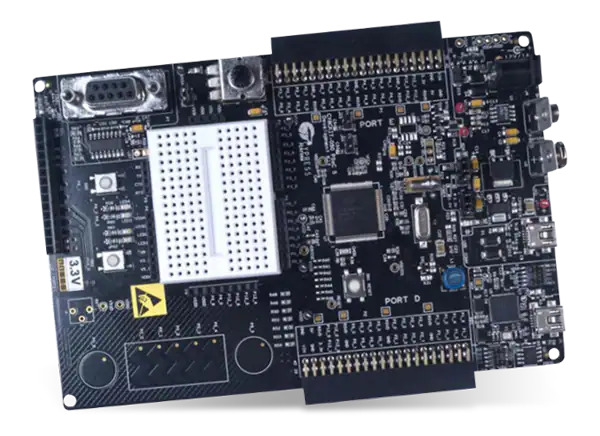
We used a PSoC 5LP Big Board for LCD control and ADC readings, and learned about capacitive sensing.
4. Final Project Takeaways
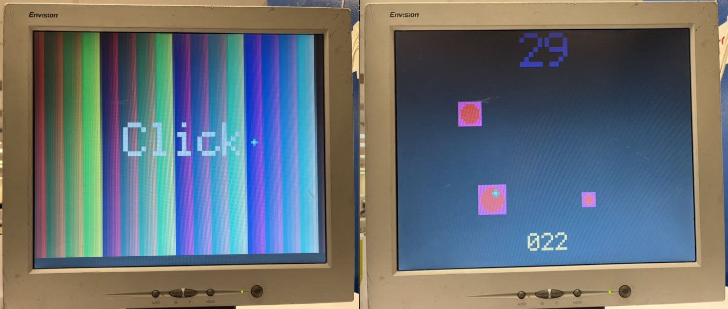
My final project ended up being an Aimlabs style game running on the PSoC with a VGA display, sound effects from the lab kit speakers, and a PS2 mouse! It was a pain getting the PS2 to work correctly, but I’m proud of it - especially considering the time constraint I was under this semester.
The final project proposal phase involved defining a project scope and identifying hardware. We were advised to start ordering parts quickly by contacting the professor and TAs, focusing on exact part numbers with Amazon links. The budget was around $10-25 per student, but there may be some flexibility. We were encouraged to use a specific TFT display and avoid trying to write our own driver. We needed to think about the versatility of the PSoC, the project component difficulties, and ensure everything is available and compatible with what we have.
We should frame our project as having a modest risk. The live demo was important and would need a full explanation, along with the notebook. The notebook will need to show evidence of testing, like wiring diagrams and scope shots. We need a good hardware description diagram and a block diagram or FSM for software.
Bluetooth requires an HC module on both sides, but one of them has to initiate communication. PSoC doesn’t have built in bluetooth.
We also considered using a VGA display, which could give us the flexibility to use a bigger screen. We would have to use a 74LS245 chip and be prepared to manually program the VGA connector. We also needed to figure out what to do with an included mechanical keypad, instead of the PS2 keyboard. We also considered using a nerf gun and the MPU6050 for aiming.
We broke up the project into smaller stages/exercises, similar to how the labs were structured, to make the scale of it manageable. This, combined with an all nighter, made the project a success! (Not to say it wasn’t extremely tight and stressful though.)
Last updated: 29 January 2025